








Recover the FreeCAD model before changing its geometry
To recover FreeCAD files after a crash, preserve the surviving document, then check AutoRecovery and existing document backups. A model that opens with a failed feature needs a different response from a deleted FCStd file. Therefore, identify which problem you actually have before repeatedly saving, recomputing, or replacing parts of the design.
An FCStd document holds more than the shape visible in the viewport. Its feature tree can include sketches, constraints, expressions, references, and dependent operations. By contrast, an exported solid may preserve geometry without those relationships. This guide separates native document recovery from geometry salvage, so you can choose a result that fits the work you still need to do.
First record what disappeared
Write down the last operation you remember, such as adding a pocket, changing a dimension, or linking another document. Also note whether FreeCAD crashed, the computer restarted, or a normal save replaced the wrong file. These details help you choose between crash state and earlier saved versions. A backup from before a dimension change may solve an overwrite, while a crash candidate may contain later unsaved work.
Keep the original folder structure when you make a working copy. Include linked FCStd documents and source geometry that the assembly uses. A single recovered file can appear incomplete if its external references remain elsewhere. Also preserve the installed FreeCAD version and relevant workbench names. Opening the candidate in a different environment can introduce new warnings that obscure the original problem.
Free route 1: use an available AutoRecovery candidate
- Preserve the original model directory and any recovery files before cleaning temporary storage.
- Start the FreeCAD version used for the affected design and inspect any recovery offer.
- Recover the relevant document without replacing your only saved FCStd file.
- Save the candidate under a new FCStd name in a separate working folder.
AutoRecovery depends on settings and recovery data that existed before the interruption. Turning it on now cannot create a snapshot of a session that disappeared. If the startup dialog offers several documents, compare their names and timing with the affected job. Also recover related documents when necessary, because the newest assembly file alone may still reference an older part.
Inspect the candidate before a full recompute
First examine the tree and the last expected features. Check whether the sketch and operation you were editing actually exist. Then note warning icons or missing references. A successful opening only confirms that FreeCAD can read enough of the document to display it. It does not prove that every operation or dimensional relationship survived in the intended state.
Save a separate baseline before making repairs. After that, test recomputation in the working copy and watch where the first error appears. Later errors may follow from one earlier failure. For example, a broken sketch support can cause a pad and several downstream features to fail. Correcting the first cause gives you a clearer assessment than deleting every red item in the tree.
Free route 2: open an existing document backup
- Show full file extensions and inspect the original model folder for existing FreeCAD backups.
- Copy likely candidates elsewhere and preserve their original names in a note.
- If necessary, rename only a working copy so its extension ends in .FCStd.
- Open each candidate, compare the relevant features, and save the best verified result separately.
FreeCAD backup naming varies with version and document preferences. You may encounter numbered FCStd backups or timestamped FCBak files. Use the actual files and the installed version’s documentation rather than expecting one universal filename. A suffix change only makes a genuine candidate easier to open; it does not repair missing bytes or turn an unrelated export into a native document.
Choose the right design state
Compare the feature content with your last known milestone. A later timestamp can belong to a save made after the unwanted change. Conversely, an earlier backup may preserve the correct reference structure while lacking a final cosmetic operation. Create a comparison note with the candidate name, important dimensions, last valid feature, and any unresolved external reference.
Do not repeatedly save the original merely to see whether a new backup appears. That can rotate the history you want to preserve. Instead, compare copies outside the original folder. Once you identify a useful backup, add missing later work deliberately in a new document. Keep the older candidate unchanged so you can revisit a dimension or relationship if a later repair fails.
Free route 3: recover access to a linked document
- Identify the exact unavailable FCStd reference in the affected assembly.
- Search the original project directories and existing delivery packages for that document.
- Copy the assembly and its matched linked parts into a separate recovery workspace.
- Reconnect the correct source and test placement, dimensions, and dependent features.
This route addresses an available document at the wrong path. It does not recover a genuinely deleted part merely by updating a link. Also avoid substituting a similarly named component without checking its design. Two brackets may share a name while using different hole spacing. A replacement that looks plausible in the viewport can therefore produce an incorrect assembly or manufacturing output.
Check placement and units
Inspect a linked component’s coordinate system and assembly placement. Then measure a distinctive dimension and a critical interface. If a part appears far from the assembly, investigate its transform before moving it by eye. A manual visual adjustment can hide the reference problem while breaking the design intent that later operations rely on.
Check the linked document in its own window as well. This separates a problem inside the component from a problem in the assembly relationship. If the component opens correctly but the assembly remains wrong, focus on the link and placement. If the component itself lacks the intended feature, compare its native backups. Those are separate recovery decisions even when the visible symptom is the same missing shape.
Free route 4: salvage an existing geometry export
- Locate an existing STEP or other appropriate geometry export from the same design revision.
- Import a copy into a new FreeCAD document and check the result.
- Measure critical dimensions and inspect the solids needed for the next task.
- Label the result as geometry salvage and retain its source beside the recovered document.
An existing export can be valuable when you need to inspect a part or resume a limited downstream task. However, it may not contain the original sketches, constraints, expressions, or editable feature sequence. Do not describe the imported solid as a complete restoration of the FCStd design. Its usefulness depends on whether the surviving geometry supports the work you actually need to perform.
Decide whether geometry is enough
A shop may need an approved outer shape for reference while an engineer needs to change a parametric pattern. The export may serve the first purpose but provide a poor starting point for the second. State that distinction before rebuilding. Otherwise, you may spend time modifying a simplified solid when a native backup would preserve the intended design more accurately.
Also compare the export’s revision with drawings or delivery notes. An old STEP file can look complete yet omit a late clearance change. Measure the feature that distinguishes the revisions, not just the overall dimensions. If you cannot establish which design it represents, retain it as an uncertain candidate and avoid treating it as an approved manufacturing source.
Diagnose a file that opens but looks empty
An empty viewport does not necessarily mean that the document lost its objects. Inspect the model tree, object visibility, active body, and view framing before attempting disk recovery. Also check whether the feature you expect belongs to another open document. A visibility or navigation issue can produce the same first impression as a damaged file.
Select a known object in the tree and inspect its properties. If it exists with plausible dimensions, investigate visibility and camera framing in the copied document. If the object is absent from the tree, compare saved versions instead. Changing display settings cannot recreate a sketch or operation that the document never recorded.
For assemblies, identify whether the missing appearance comes from an unresolved external file. Keep unavailable references in your notes while checking the source folder. Deleting them to tidy the tree removes useful clues. Once the source resolves, inspect both the component and the assembly because a display correction alone does not establish that the correct revision loaded.
Handle recompute errors without losing useful features
A recovered model can contain a valid early design and an invalid later operation. Work from the first failing feature toward the end of the tree. For each failure, inspect its inputs and error message before changing anything. This preserves useful design intent and helps distinguish a missing reference from an environment or workbench difference.
Test one repair at a time
Suppose a fillet fails after you change a supporting sketch. Save a baseline copy, inspect the upstream shape, and test a narrow correction. Then recompute and compare the intended dimensions again. Avoid unrelated edits without checkpoints, because a later successful recompute may conceal an unintended geometry change introduced during the repair.
If an operation depends on an addon workbench, document that dependency before attempting a conversion. Another installation may lack the tools needed to interpret or edit the object fully. Recovering the file and restoring the working environment are related but separate jobs. Use a compatible environment for assessment, and preserve the original document before experimenting with migration.
Inspect an FCStd container only on a copy
An FCStd document is a structured container, so archive inspection can reveal whether its entries remain readable. Preserve the original before opening a copied document with an archive tool. The presence of a thumbnail or XML entry is only a clue. It does not prove that the entire parametric design and associated shape data survived intact.
Keep previews separate from model data
A thumbnail can help identify a candidate by appearance, but it is not a substitute for the editable document. Similarly, a readable shape entry may provide limited geometry without the original feature relationships. If you salvage anything from the container, record its role explicitly. Do not treat a recognizable preview as proof that FreeCAD can restore the complete model.
Avoid casual edits to internal XML or repacking as a first response. Incorrect structure can create a new problem while hiding the original one. An experienced investigation may use the documented format and appropriate utilities on copies, but the result still needs native validation. Archive readability and engineering correctness answer different questions.
A worked recovery after a bracket-model crash
Imagine that FreeCAD crashes after you revise a mounting-hole pattern and add a fillet. Preserve the project, then compare AutoRecovery with the last saved backup. Identify the candidate containing the intended hole spacing. A newer candidate with a failed fillet may still preserve the correct sketch, while an older fully recomputed model may contain the wrong pattern.
Keep the important dimension as the acceptance target
Use the intended hole centers and part thickness as concrete checks. Then investigate the fillet in a working copy without changing those dimensions. If the fillet must be rebuilt, record that edit separately from the recovered sketch. This makes the result understandable and prevents a convenient older model from silently replacing the required engineering change.
Next reopen the saved recovery and inspect any drawing that depends on it. Compare views, dimensions, and section details before generating a new delivery export. A recovered solid can differ from an older drawing even when both files open normally. Keeping the accepted native model and regenerated output aligned is part of completing the recovery.
Decide which FreeCAD candidate supports the next engineering task
A useful recovery target is more specific than getting the model to open. Decide whether you need to edit dimensions, inspect an assembly, regenerate a drawing, or recover a shape for reference. Then assess candidates against that target. For example, a native backup with the correct sketch can support a pattern change, while a visually complete imported solid may only support measurement. This decision helps you choose between candidates without discarding a source that could still serve another part of the job.
Inspect constraints and expressions that carry design intent
For a dimension-driven part, inspect the sketch constraints associated with the missing change. Compare their values with the intended specification and check whether expressions refer to the expected objects or properties. A model can display an acceptable shape while a driving relationship differs from the original design. That difference may become visible only during the next edit. Therefore, test a small, reversible parameter change in another working copy when appropriate, then verify that the expected dependent geometry follows it.
Also inspect the distinction between a displayed dimension and the relationship that drives it. A drawing annotation can show the desired number while the underlying model still uses an older value. Compare the actual model measurement and the relevant constraint rather than treating the annotation as proof. If the relationship remains uncertain, keep the recovered model for reference and resolve the design question before regenerating an approved output. This is especially useful when you have several backups that differ only in a small dimensional revision.
Compare a multi-part recovery as a set
An assembly can contain individually valid documents from incompatible revisions. Create a simple list of the required components and the candidate chosen for each. Then compare the interfaces between them, such as a shaft diameter, hole pattern, or mating face. A part that is correct in isolation may still be wrong for the recovered assembly. Checking the interfaces makes the recovery target concrete and reveals revision mismatches that a general viewport inspection can miss.
Use a fit question to resolve ambiguous revisions
Suppose two recovered bearing blocks have the same outer shape but different mounting-hole positions. Compare the mounting surface and the corresponding holes in the baseplate. Then check the revision notes or drawing that establish the intended configuration. Do not choose the block with the later filesystem date merely because it appears newer. A copied file can acquire a misleading date, while the geometric relationship provides direct evidence about whether the component belongs in the selected assembly.
Keep rejected assembly candidates in a separate evidence folder with a brief reason. For example, note that one bracket matches an older baseplate but not the accepted mounting pattern. This prevents the same ambiguous file from re-entering the working assembly during a later repair. It also makes the recovery easier to hand over: another designer can see which sources were useful, which were incompatible, and which question still requires confirmation from the design specification.
Recover a drawing without confusing it with the model
A surviving drawing can preserve dimensions, views, notes, and revision clues even when the native model is missing. Use it to identify the intended geometry and evaluate recovered candidates. However, a drawing is not necessarily an exhaustive description of every surface, feature, or modeling relationship. Before rebuilding, identify which dimensions and details it actually specifies. Any remaining geometry may require a design decision rather than simple transcription from the page.
Check drawing dependencies after native recovery
If the drawing belongs to the recovered FCStd document or references related model content, inspect its views after recomputation. Compare the displayed geometry, dimension attachment, and section details. A view can look familiar while an annotation points to a changed edge or an outdated feature. Save a new review output and inspect the actual page. This tests whether the recovered native document supports its downstream drawing, not merely whether the solid appears in the 3D window.
For a drawing that survives only as PDF, retain the original PDF as a reference and keep any rebuilt native drawing separate. Compare critical dimensions and notes manually. Do not imply that importing the PDF recreates the original parametric model or all drawing relationships. A careful reconstruction can still be useful, but it should carry a clear record of the source dimensions and any unresolved assumptions. That record matters when the next engineer changes a feature that the PDF never fully described.
Use a staged acceptance check for repaired feature trees
First verify the last known valid feature, then the repaired operation, and finally the downstream geometry. This sequence helps isolate where a mismatch begins. For each stage, compare the relevant dimensions and object relationships in the working copy. If a later feature fails, preserve the successful earlier stage before trying another repair. You then retain useful recovered work even if a more complex finishing operation remains unresolved.
Evaluate small details that change downstream use
Inspect holes, pockets, thin walls, and edge treatments that matter for the intended output. A simplified candidate can preserve the overall silhouette while losing a small but important feature. Also compare any selected-face or selected-edge dependencies after repair. A recomputed model can be internally valid yet apply a later operation to a different geometric element than intended. The appropriate check is the resulting design detail, not simply the absence of a warning icon.
Finally, define what you will accept before sending the recovered model onward. For a reference task, verified shape and dimensions may be enough. For continued parametric design, you may also need stable constraints, expressions, and linked documents. Record the scope of acceptance beside the saved milestone. This makes a partial but useful recovery honest and prevents a geometry-only candidate from becoming an unquestioned editable master in a later engineering workflow.
Compare model history against a dimensional change log
If the project has a change log or marked-up drawing, extract the dimensions that distinguish the intended revision. Compare those values directly in the recovered model and record the result. Also identify any note that describes a functional change rather than a dimension, such as adding clearance for a cable. A candidate can match overall size while missing that local feature, so use the change’s actual purpose to guide inspection.
Keep rebuilt features traceable
When you recreate a missing operation, give the recovery note enough detail to identify it later. State which surviving sketch or geometry supplied its input and which specification guided the change. Then save a checkpoint and compare downstream features. This turns reconstruction into a controlled modeling step and prevents later users from assuming that every feature came unchanged from the recovered historical document.
A useful final comparison includes the native tree, the critical measurements, and a fresh output from the accepted model. Each confirms a different part of the design. If one remains uncertain, preserve the accepted partial result and identify that limitation. You can continue suitable reference work while keeping any unresolved manufacturing or parametric-editing question visible.
When disk recovery is appropriate for FreeCAD files
PandaOffice Drecov is relevant when a saved FCStd file or its existing backup was deleted from readable storage and the native routes did not supply it. It cannot manufacture an unsaved sketch that never reached disk. Also reduce writes to the affected location. Repeated read failures or disconnections call for storage assessment before a routine software scan.
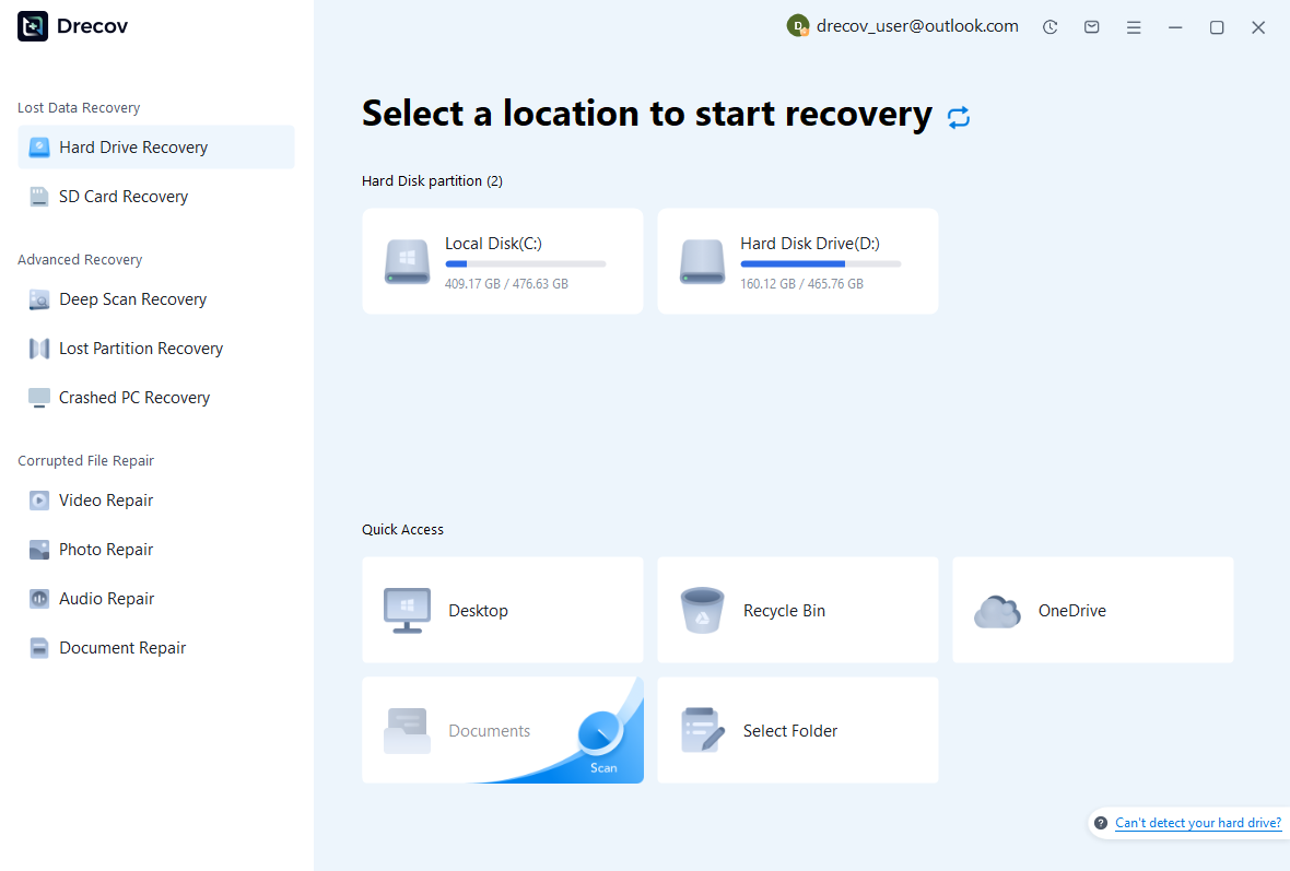
Step 1: scan the storage that held the model
Choose the drive or partition containing the native document and actual backup location. Keep recovery output away from the affected storage. Note whether you need the assembly, linked parts, or both. The source-selection illustration shows the matching language interface; it does not establish that your particular FCStd document is recoverable.
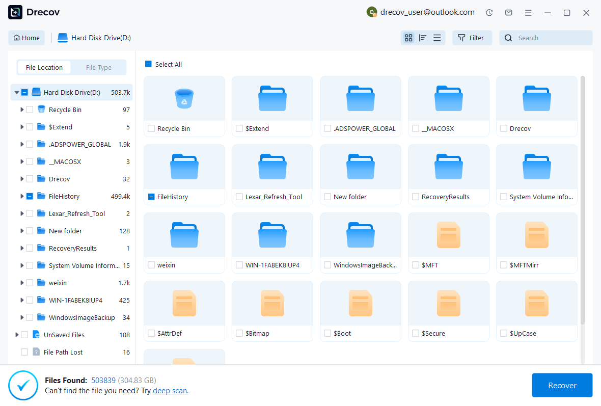
Step 2: compare native documents and backups
Review available names, paths, sizes, dates, and file details for FCStd and related candidates. Preserve several plausible revisions when useful, because the latest timestamp can follow an unwanted edit. Do not assume a generic preview validates a parametric model. FreeCAD must read the candidate and expose its feature tree before you can assess the actual design content.
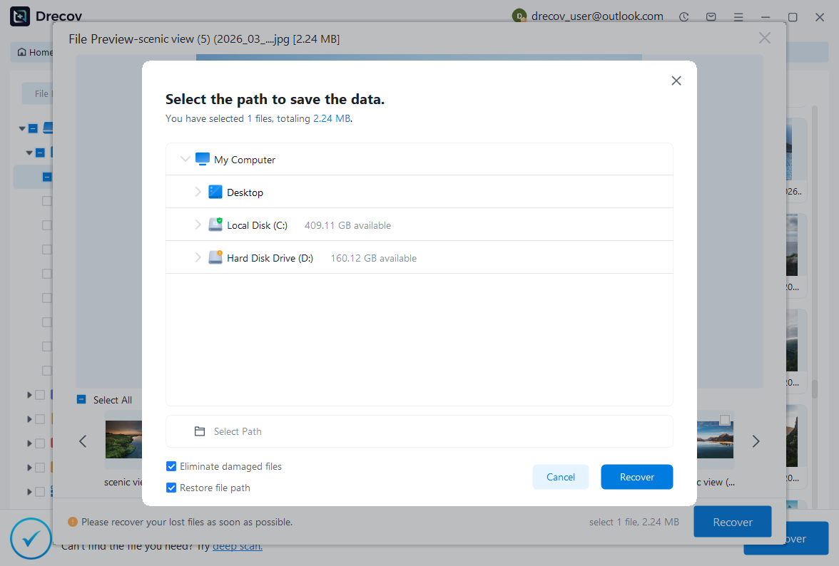
Step 3: restore elsewhere and validate the model
Recover selected documents to another healthy destination and preserve their relative paths. Open working copies in a compatible installation, then inspect references, recomputation, and critical dimensions. Keep uncertain candidates separate from the accepted model. A complete filename or successful scan does not establish that the intended geometry and editable relationships survived.
Confirm the recovered design before resuming work
Reopen the saved recovery after a fresh launch and repeat the critical checks. Then compare a representative drawing or export with the intended geometry. This catches references that a previous session might conceal. Keep a short record of the source candidate and repairs, so another designer can distinguish recovered history from newly rebuilt features.
Preserve a useful next checkpoint
Save a clearly named native milestone and retain the recovered source separately. If you create a STEP or drawing for review, record which native document produced it. Also test the configured backup and AutoRecovery behavior on a disposable model. A practical test shows where files actually go and whether copied candidates reopen.
Treat a geometry-only result as limited salvage until it fits the intended task. If no candidate contains the missing sketch or operation, document that gap. Rebuilding from dimensions or drawings may still be possible, but it is new modeling work. That distinction prevents an uncertain reconstruction from becoming the next project’s unquestioned baseline.
Related recovery resources
Explore the relevant recovery options: Hard drive recovery, External hard drive recovery.
For another recovery case and its practical checks, read the related recovery guide.
Check the vendor guidance for the installed version: official recovery documentation 1, official recovery documentation 2.