







Start with the KiCad project rather than one missing file
To recover KiCad projects, preserve the whole project folder, identify the KiCad version, and compare existing native history or archives before scanning the drive. A schematic, board, and project settings belong together. Therefore, restoring only the file that looks newest can leave you with a design whose electrical intent and physical layout no longer match.
A missing recent change does not always mean that the design file was deleted. You might have opened another project directory, an older archive, or a board from a different revision. First record the actual path shown by the application. Then compare a distinctive component or connection with your last known milestone. This gives the recovery a concrete target instead of relying on filenames alone.
Preserve the design and its context
Copy the original directory, including hidden project history when present, before restoring a snapshot. Also retain local symbol libraries, footprint libraries, custom rules, and any referenced mechanical models. These dependencies can explain why an otherwise valid design displays missing items. Keep this preserved copy separate from the directory where you will test recovered candidates.
Record whether the interruption happened during schematic editing, routing, library editing, or a project save. Also note the installed KiCad major version. Native backup behavior differs between releases. For example, current documentation describes incremental Local History, while older installations may use ZIP project backups and separate autosave behavior. Follow the route your installation actually supports rather than looking for a panel from a different release.
Free route 1: restore an existing Local History snapshot
- Preserve the full project, including its hidden history data, in a separate location.
- In a version that supports incremental backups, open the Local History panel from the View menu.
- Inspect the available snapshot times and the files that changed in each snapshot.
- Restore a suitable snapshot in the working copy, then save and inspect the complete design.
This route requires history that KiCad already recorded. Enabling incremental backups after the loss will not reconstruct an earlier routing session. Also verify which files the candidate contains before restoring it. A snapshot taken after a schematic save may differ from one taken after a board save. The useful question is whether the candidate contains the missing design work and its matching dependencies.
Compare snapshots by circuit content
Choose a small set of identifiers that distinguish the intended revision. For instance, inspect the reference designator of a recently added connector, its pin mapping, and the corresponding board footprint. Then compare the same identifiers across candidate snapshots. A timestamp is a useful sorting clue, but these design details show whether a snapshot actually contains the change you need.
Avoid manually rewriting the hidden history repository during recovery. Let the installed KiCad interface handle its own history format. If you also use an ordinary Git repository for the design, keep that separate in your notes. An application-managed history folder and your reviewed engineering commits can represent different checkpoints, even when both ultimately use version control technology.
Free route 2: extract an existing ZIP backup
- Find the configured project backup location and copy the relevant ZIP archives elsewhere.
- Inspect archive dates and contents without extracting over the live project directory.
- Extract each useful candidate into its own clearly named folder.
- Open the project in KiCad and compare its schematic, board, rules, and local libraries.
The backup location and retention settings depend on the installed release and configuration. Therefore, inspect the actual project and user settings rather than assuming every backup sits beside the board. If several archives survive, preserve them before launching repeated saves. Backup rotation can remove older candidates, and the oldest useful design may be more valuable than the latest damaged state.
A hierarchical schematic can depend on several sheet files. If you recover only the top-level sheet, it may open while showing incomplete subcircuits. Check the sheet hierarchy and inspect every referenced sheet needed by the design. Also verify that local library files belong to the same recovered revision. A library from another job can create confusing symbol or footprint differences.
Compare custom design rules and net classes as well. A board can look visually complete while using different clearance or width settings. That matters when you run checks or regenerate manufacturing output. Recovering the geometry is only part of restoring a useful engineering project. The design’s constraints and definitions help determine whether later edits remain consistent with the intended circuit.
Free route 3: open a previously created project archive
- Locate an existing KiCad archive or an authorized project package from the relevant milestone.
- Copy the package and extract it into a new recovery directory.
- Open the project file and inspect the expected design files and dependencies.
- Compare the archive’s revision against engineering notes before using it as the new baseline.
An archive previously sent for review can provide a stable checkpoint when automatic history is unavailable. However, a delivery package may omit later edits or external dependencies. Do not assume it contains everything merely because the ZIP opens without an error. Inspect its actual schematic, board, rules, and libraries, then identify precisely which parts of the missing work it can supply.
Use fabrication output as evidence
Existing Gerbers, drill files, assembly drawings, and a bill of materials can help you compare revisions. They can show whether a connector moved or a component existed at a particular milestone. However, these outputs do not automatically recreate the original editable schematic and board relationships. Retain them as evidence and limited salvage sources rather than presenting them as a complete native project restoration.
For example, a Gerber image may reveal a trace route that you need to redraw in a recovered older board. That is manual reconstruction based on an output, not direct recovery of the routing object. Record the distinction and run the design checks again afterward. Otherwise, an apparently faithful visual reconstruction can still omit net assignments, rules, or copper connectivity.
Free route 4: inspect an existing reviewed Git revision
- Preserve current working files and any uncommitted design changes before using version control.
- Inspect the existing repository history for a known schematic and board milestone.
- Create a separate working copy or branch for the candidate revision.
- Open the complete recovered project and compare both electrical and physical design details.
Git can supply files that were actually recorded in a surviving commit. It cannot retrieve an uncommitted routing session merely because the project directory contains a repository. Also avoid discarding current modifications while searching older history. A useful recovery may combine an older valid circuit with later work that still survives in another file, so preserve both before deciding what to retain.
Reconcile mixed revisions deliberately
Suppose the schematic contains a new sensor but the recovered board predates it. Do not immediately update the board and accept every change. First compare the intended component identities, net names, and footprint assignments. Then save a checkpoint and apply the required update in a working copy. This helps you distinguish necessary reconciliation from an accidental design change introduced by the recovery process.
If the project uses a shared library, identify the library revision expected by the recovered files. An ordinary project commit may not include an external library directory. Document that gap instead of silently substituting a different symbol definition. Small library differences can affect pin types, pad numbering, or physical dimensions, so they deserve a concrete check before the design resumes normal use.
Diagnose an apparently empty schematic or board
First confirm that you opened the intended file from the intended project. Then inspect the visible sheet, board layer selection, view framing, and any messages about missing dependencies. A wrong sheet or hidden layer can make valid content appear absent. Conversely, a file with genuinely missing objects needs a historical candidate rather than repeated changes to the display.
Distinguish a library warning from lost design data
A missing library warning does not by itself establish that the schematic or board file lost its placed content. Inspect the affected object and compare it with the expected library definition. Preserve the existing instance before replacing it. Updating a symbol or footprint during recovery can change the design, so treat that as a separate, reviewable operation.
Also check custom search paths and project variables after moving a recovered folder. Relative references can remain valid when the package structure stays intact, while absolute paths may still point to the original machine. Correct the specific dependency and test again. Do not rename an entire library tree simply to remove one warning without checking which other projects use that path.
A worked recovery for a partially routed controller board
Imagine that a controller board crashes after you route a new connector, but the latest manual save predates the route. Preserve the project and compare the available native history first. Identify a candidate containing both the connector footprint and the new tracks. Then inspect the schematic connection for that connector rather than assuming the routed copper proves that the circuit definition matches.
Choose between two imperfect candidates
One candidate might contain the latest routing but an older symbol edit. Another might contain the symbol correction without the route. Keep both. Compare the intended pin assignments and determine whether you can safely transfer the missing work into a new recovery branch. Do not repeatedly replace the live directory, because that makes it harder to track which state supplied each part of the final project.
After reconciliation, inspect the connector’s pad numbers, net assignments, and physical orientation. Then review nearby copper, mounting clearances, and the board outline. These checks target the actual missing change. They provide stronger evidence than merely opening the project and observing that the familiar board shape appears on screen.
Validate the recovered schematic and board
Run the appropriate electrical and board design checks in the recovered working copy. Review each reported issue in context rather than deleting warnings to obtain a clean-looking report. A check can reveal mismatched connections or rule violations, but it cannot decide every aspect of the circuit’s intended behavior. Compare the result with the design notes and the last approved revision.
Inspect changes beyond automated checks
Check component values, footprint assignments, connector orientation, and critical net labels. Then compare dimensions and mechanical constraints for the board. A syntactically valid project can still contain the wrong resistor value or an older mounting position. These are revision problems rather than file-format errors, and they require a content comparison against the intended design.
Regenerate review outputs only after you accept the recovered native state. Keep them in a new output directory with the recovery revision clearly identified. Mixing newly generated Gerbers with older drill files can create an ambiguous manufacturing package. A clean recovery folder and a consistent set of outputs make it easier for another engineer to review exactly what you restored.
Build a KiCad revision comparison around one circuit change
Choose a small circuit change that identifies the intended design, such as adding a protected power input or changing a connector pinout. Inspect that change in the schematic, then locate the corresponding physical implementation on the board. Record the expected reference designators, values, nets, and footprints. This focused comparison gives you stronger evidence than a broad claim that the recovered board looks familiar, especially when several archives contain nearly identical layouts.
Trace the recovered connection from symbol to pad
For a changed connector, compare the symbol pin numbers and the intended signal names. Then inspect the assigned footprint and the board pad numbers. Finally, review the copper connection and the connector’s orientation relative to the board outline. Each step checks a different relationship. A correctly named net does not by itself prove that the physical connector presents the intended signal on the expected pin, particularly after mixing historical schematic and board candidates.
Also compare any labels that changed during the revision. A renamed signal can leave you with superficially similar circuitry but different connectivity expectations. Keep the recovered design’s actual net information visible during review. Do not redraw wires merely to make the schematic resemble an older PDF without checking their electrical meaning. If the historical evidence conflicts, preserve both candidates and identify the design question explicitly before proceeding to manufacturing output.
Recover local libraries as part of the design evidence
Project-local symbols and footprints can preserve definitions that differ from the currently installed global libraries. Keep those local files with the recovered project, and record the library tables or path variables that reference them. Then inspect important custom parts in the design. A missing library path can create a warning without deleting a placed instance, while an automatic update can change that instance. Those possibilities require different actions and deserve separate checks.
Compare custom footprint geometry before replacement
For a custom connector or mechanical component, compare pad dimensions, spacing, numbering, and any critical courtyard or outline information. Use the component specification or a known approved revision when available. Replacing the footprint with a similarly named library item can remove a warning while introducing a physical mismatch. Therefore, preserve the recovered instance and test any proposed replacement only in a separate working copy where you can inspect the resulting differences.
A recovered 3D model can help with mechanical review, but it is not a substitute for checking the actual pads and board dimensions. Conversely, a missing 3D model does not automatically mean that fabrication geometry is absent. Document which dependency affects visualization and which affects the electrical or manufacturing design. This makes the remaining work clearer and prevents a cosmetic warning from driving unnecessary changes to a valid footprint.
Handle a recovered hierarchical schematic deliberately
Inspect the root sheet and each referenced child sheet, noting whether the recovered set contains them all. Then compare sheet connections and identifiers that link the hierarchy. A top-level drawing can open while a child circuit remains unavailable. Keep that missing reference rather than replacing it with an empty sheet just to remove the warning. The original reference helps you identify the correct historical file and preserve the intended structure.
Review repeated circuitry in its project context
When a design uses repeated sheets, inspect the instances and their component identities after recovery. A candidate may contain the right subcircuit but associate it with a different instance or revision. Compare the intended channels and board placement before accepting it. This is a content check that automated syntax validation cannot fully replace, because several structurally valid configurations may still represent different engineering decisions.
If only part of the hierarchy survives, keep a clear inventory of recovered and missing circuits. You may still preserve the valid power section or interface circuitry while rebuilding another sheet from approved references. Record that reconstruction separately and rerun the relevant electrical checks afterward. This provides a useful partial recovery without presenting a newly recreated subcircuit as an untouched historical source.
Review manufacturing output from the accepted native project
Once you choose and validate the native baseline, generate a fresh, consistent output set into a new directory. Inspect the board outline, copper layers, solder-mask openings, drill data, and any assembly information required for the actual job. Keep these outputs associated with the accepted recovery revision. A folder that mixes files from several historical generations can be ambiguous even when every individual file is readable.
Use an independent visual comparison for the changed area
Compare the regenerated output around the circuit change that motivated recovery. For a moved connector, inspect its physical orientation, nearby clearances, and hole positions. For a rerouted power path, inspect the intended copper and associated planes. This connects the native design check with the deliverable that another person will use, and can reveal a mismatch that remains unobvious in the general board view.
Finish by recording any limits that affect continued work. For example, the board may be electrically verified while one optional 3D reference remains unavailable, or an older archive may still lack a documented late component change. Keep those facts beside the accepted project. Clear scope makes the recovery useful for review and prevents a plausible-looking historical board from being sent onward as if every intended revision had survived.
Review copper zones and board boundaries after recovery
Inspect copper zones and their intended nets in the recovered board. Then refresh them in a working copy using the normal application workflow and compare the resulting geometry. A familiar board outline does not establish that zone settings and clearances match the intended revision. Also check cutouts and mounting features that constrain the layout, because a small mechanical difference can affect the usefulness of an otherwise valid routing recovery.
Keep the fabrication decision separate from file readability
A project that opens is ready for engineering inspection, not automatically ready for fabrication. Compare the accepted board with the relevant electrical and mechanical requirements, then generate one consistent output set. If you reconstructed a connection from a PDF or Gerber reference, identify that work in the review note and verify its net relationship. This makes the remaining engineering judgment visible instead of hiding it behind a successful file-open result.
For a mixed-revision recovery, retain a short explanation of why the selected schematic and board belong together. Include the distinctive connector, signal, or component checks that established the match. Then reopen the saved project and inspect those items again. This gives another engineer concrete evidence to review and reduces the chance that an older, similarly named board re-enters the workflow later.
When disk recovery can help a KiCad project
PandaOffice Drecov can be considered when saved KiCad files or existing backup archives were deleted from accessible storage and the native routes did not supply them. It cannot recreate circuit work that never reached disk. Also avoid writing new project files onto the affected storage, because those writes can reduce the chance of retrieving deleted design data.
Step 1: identify the original design location
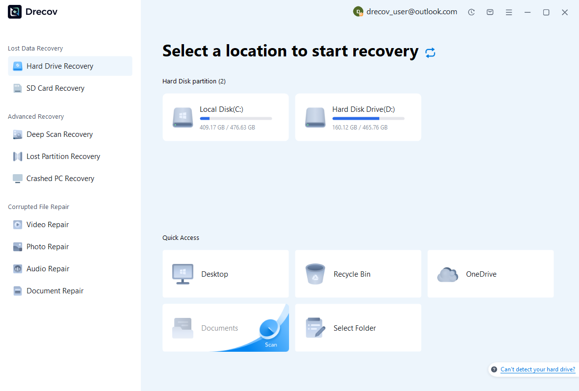
Select the drive or partition that contained the KiCad project and its configured backups. Include the possibility that the backup location differs from the design folder. Use another destination for recovered files. If the storage repeatedly disconnects or reports read failures, assess that condition before treating it as a routine deleted-file search.
Step 2: collect a coherent set of candidates
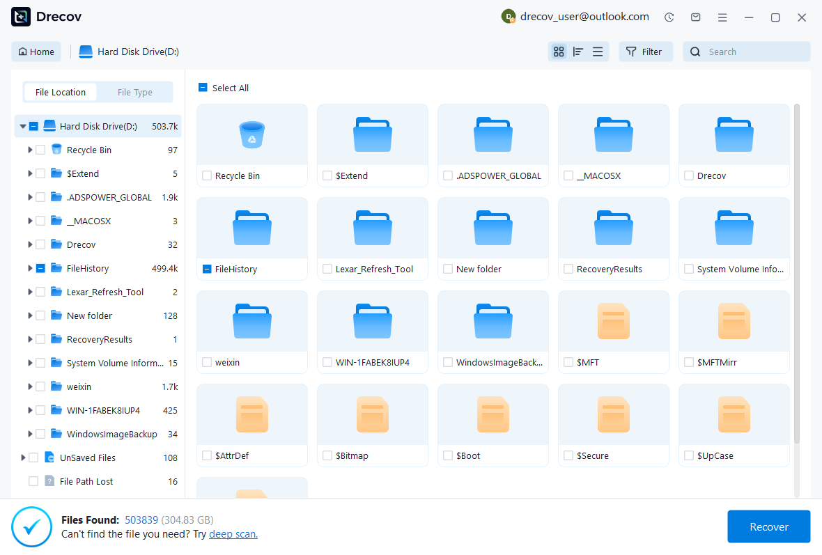
Search available results for the project, schematic sheets, board, and relevant ZIP archives. Compare names, paths, sizes, and dates, and preserve several plausible revisions when necessary. A scan result alone cannot establish that a schematic and board match. Keep their source details so you can perform that comparison in KiCad after recovery.
Step 3: recover elsewhere and run design checks
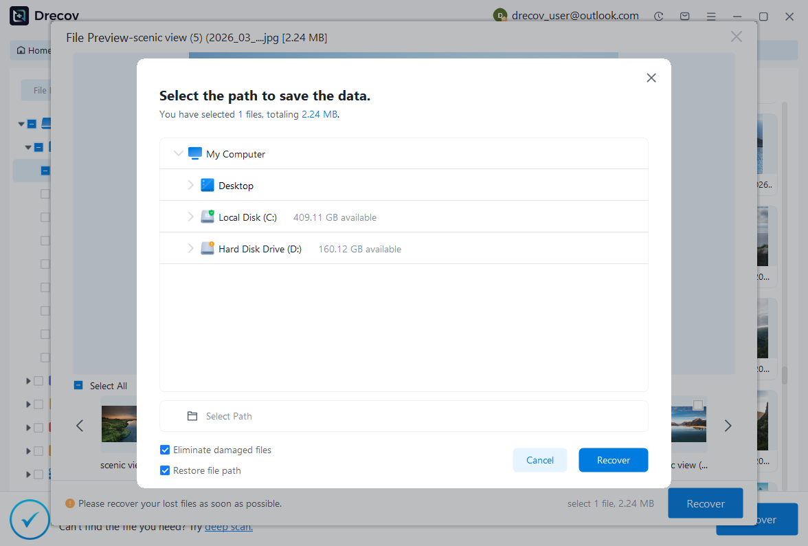
Save selected candidates to a separate healthy destination and reconstruct their relative directory structure. Open copies in a compatible KiCad release, inspect the sheet hierarchy and board, and run the relevant checks. Retain uncertain files separately. The screenshot workflow illustrates storage recovery; the actual design assessment requires the engineering application and a comparison with the intended circuit.
Make the recovered revision a clear engineering milestone
Once the checks pass, reopen the saved recovery project and confirm that local libraries and external models still resolve. Then record which snapshot or archive supplied the baseline and which edits you reconstructed. This gives the next engineer a useful account of the design state instead of a folder full of unexplained candidates with similar names.
Test future history with a disposable project
Create a small test project and verify how your installed release stores its configured backups. Make a harmless change, save it, and confirm that you can locate and open the resulting historical candidate. Also check retention and available space. This practical test shows what protection you actually have without experimenting on the newly recovered production board.
Keep the accepted native project separate from the preserved evidence and rejected candidates. If a missing route or sheet never appears in any surviving source, say so plainly and plan the necessary reconstruction. An honest partial recovery is more useful than treating an older board as complete simply because it opens and resembles the original design.
Related recovery resources
Explore the relevant recovery options: Hard drive recovery, External hard drive recovery.
For another recovery case and its practical checks, read the related recovery guide.
Check the vendor guidance for the installed version: official recovery documentation 1, official recovery documentation 2, official recovery documentation 3.